Overview
Multi-Physics Simulation System for Continuum and Discrete Dynamics
Summary
MulPhys is a model development environment for complex multi-physics simulations. It is based on a multi-domain and multi-model approach, which enables different physical models to co-exist in different geometrical domains and interact with each other.
Introduction
The idea behind this project is to provide an object-oriented environment for multi-physics modeling. The focus of the system is on the simulation of complex discrete and continuum dynamics. The modeling framework is based on the efficient library routines for manipulating geometrical primitives, which include particles, nodes, edges, faces, and cells. There are two basic features that are inherent in all primitives: dynamic creation/destruction and dynamic connectivity. The former allows for modeling of complex events when the number of elements is constantly changing, like particle dynamics, structure failures, mechanical interactions etc. Dynamic connectivity enables modeling of complex mechanical and fluid-dynamical events with interactions between different physical entities, like particle-fluid, fluid-structure, solid-solid interactions. While broadening the scope of possible mechanical events that the system is capable of simulating these features can also be used on parallel computer platforms for dynamic load balancing.
Problem Setup
In contrast to conventional simulation environments where the simulation process involves three distinct stages: pre-processing, simulation and post-processing, MulPhys environment is based a single simulation/visualization process, where a GUI-controlled visualizer displays the state of the system at any time during the simulation. Because of the multi-model design it is possible to integrate pre- and post-processing into one continuous simulation process. For example, some elements of pre-processing, like mesh-generation, become the integral part of the simulation process, since mesh-generation itself is considered as just another model in the system. This general approach also facilitates modeling of complex systems, like those with changing geometries and moving boundaries.
Implementation
- Elements
Each geometric primitive is represented by an object of a respective class with a common parent class Element. To enable dynamic creation/destruction of the elements all objects of the same class are connected into a linked-list structure, inherited from the parent Element class.
The geo-primitives, such as Nodes, Edges, Faces, and Cells are the sub-classes of the Element. Different sub-models can handle these primitives as physical entities, which then can reveal themselves as Particles, Bonds, Membranes, and Volumes respectively. For example, the diagram below shows the configuration of the model consisting of particles (nodes), bonds (edges), and physical volumes (cells), with given interactions between the three entities.
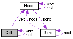
The connectivity lists themselves can be represented by arrays or linked lists. For example, in the case of unstructured tetrahedral gridding the connectivities are constant-size arrays, whereas in other cases they can be realized as dynamic linked lists (see the inter-atomic bonding problem, or structural collapse).
A library of functions to compute areas, volumes, momenta, stresses, fluxes etc. is compiled for each class of elements and used in computations of complex dynamics.
- Domains
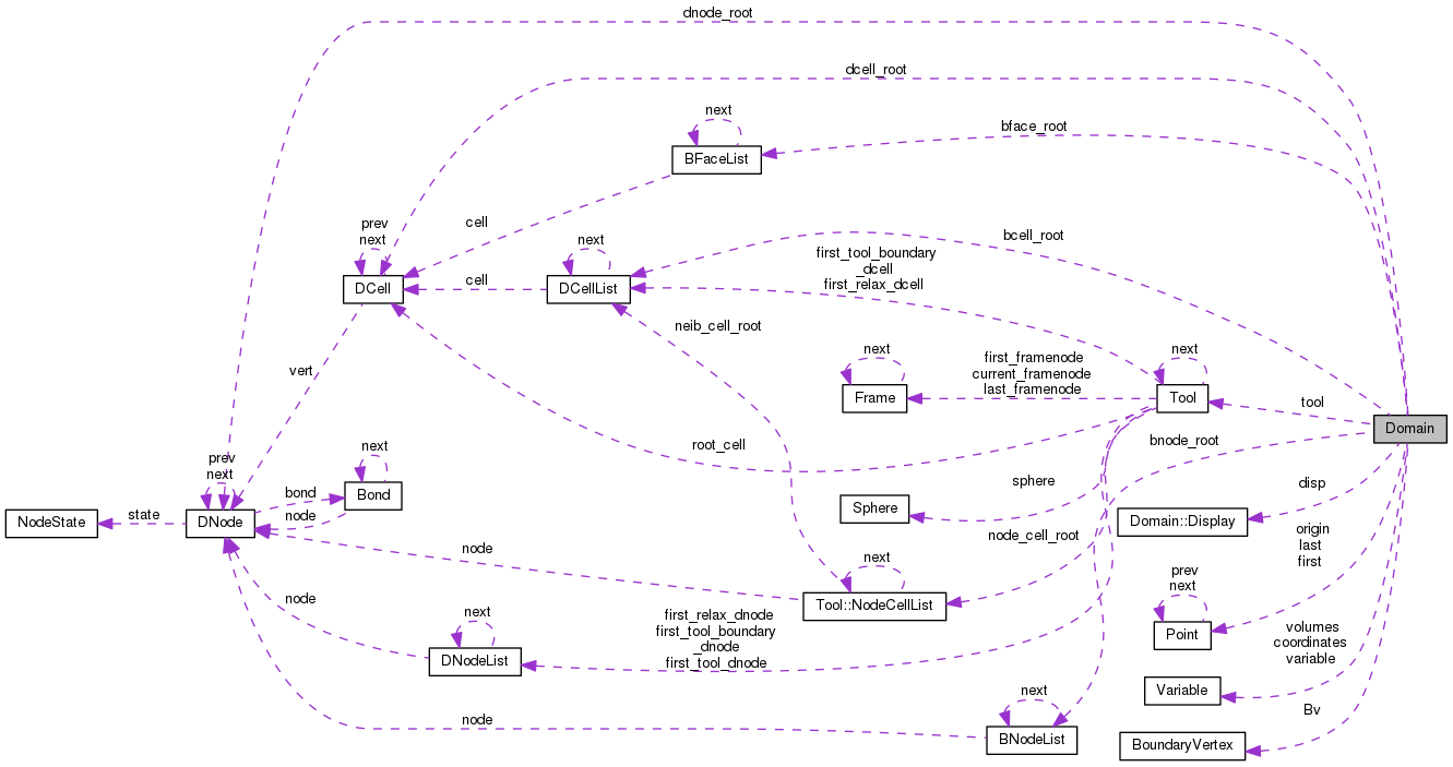
There can be any number of domains. Each domain includes a collection of elements and a corresponding physical model. For example, the geometry of a particulate flow problem is defined as a connected list of nodes and tetrahedral elements (unstructured grid) and a collection of particles (points) dynamically connected to the grid. The problem setup is completed by specifying the appropriate models of fluid and particulate flow. A class interdependence graph of a typical flow model is shown below.
- Domain coupling
Several domains can be coupled together using a DOVE scheme. This enables an interaction of different physical models with each other, and also creates a parallel simulation environment which can be easily implemented on distributed memory computer platforms.
- Model encapsulation
Each particular physical model is encapsulated into a separate C++ namespace with an interface to the main executable routine. The interface consist of standard functions, such as declarator, initializer, and iterator. Each domain contains pointers to these interface functions, which are assigned during domain initialization so as to execute specific models.
This encapsulation enables to use many different models in a single modeling paradigm. For example, in the current version the grid generator is encapsulated in a Model_Grid namespace, and implemented in a separate file. The flow-solver has a different model-space - Model-Flow, etc. This enables the coexistence of different models on different domains during one execution. All domains and geometries are specified in a separate configuration file together with information on which model is to be used at which domain.